News
See below for our latest GeMech news

What are Rigid Inclusions?
Rigid Inclusions have become increasingly more common in UK ground engineering practice, the technique allows the use of an alternative ground improvement approach on sites and in ground conditions which are not best suited to more flexible techniques such as vibro stone columns.
Most often at present rigid inclusions are formed using displacement augered methods, as this system is very well suited to the nature of ground conditions where rigid inclusions offer their greatest benefit. Although, this need not always be the case, many other traditional piling methods can be used as part of a rigid inclusion scheme, for instance –
Many more examples exist, and the technique is readily adaptable to a wide range of foundation types and structures.
In this blog we will explore some of the benefits of the Rigid Inclusion technique, along with some of the key technical considerations.
Benefits of Rigid Inclusions
Key benefits of the technique can be listed as –
Key Considerations
There are several aspects of rigid inclusion design and implementation that need to be understood when assessing the suitability of the system, some of these considerations will be discussed in more detail below.
The Load Transfer Platform (LTP) is arguably the most critical aspect of the successful design and implementation of a rigid inclusion scheme. It must be dimensioned appropriately to the size and spacing of the rigid inclusions, the stiffness of the shallow soils, and the magnitude of the applied loads.
ASIRI 2012 recommends –

The load transfer platform must exhibit high shear strength and stiffness to ensure that internal arching effects develop, and may, in the case of an LTP formed after completion of column construction, be reinforced with a geotextile layer.
In UK practice it is commonplace to form the LTP at, or near to, underside of slab level and to use it to support the piling rig during the rigid inclusion construction phase. This requires that the rigid inclusion head levels are reduced by some means after construction is complete. In the case of augered rigid inclusions this is generally carried out while the concrete is still wet, through localised excavation. The LTP is then recompacted over the rigid inclusion heads to bring it back up to the correct level. This process is clearly sub-optimal if it is not strictly controlled, as it leads to an increased potential for localised areas of LTP with reduced strength and stiffness, directly over the RI locations. The optimal solution from a design perspective is to install the rigid inclusions from a working platform of suitable thickness, at some proportion of the required final LTP thickness, to reduce the levels as described above whilst the concrete is wet, and to then build the LTP up to its full design thickness once all RI’s are installed.
When preparing a load transfer platform, or finalising proposals for RI head reduction, the elevation tolerances present in ASIRI (2012) should be recognised –

In short, RI’s must have a depth of penetration into the LTP and should be within 50mm of design level at completion.
The important thing is that this is discussed and agreed before any work begins!
ASIRI (2012) is explicit in its recommendations for maximum and minimum rigid inclusion spacings, as a function of RI size, and the proposed testing regime.
Minimum spacings –

Maximum spacings –

In UK practice, where rigid inclusions are most often installed at diameters < 500mm using displacement augering techniques, a minimum centre to centre spacing of 4 x diameter would be expected, along with a maximum spacing of 3.0m or 9m2 of foundation area per RI.
For small pad foundations supported on a single column, ASIRI (2012) stipulates that –

This, coupled with the minimum spacing criteria noted above, sets some limitations on the maximum bearing capacity that can be applied to small, isolated pad foundations.
Whilst not all the load transferred at top of LTP level will be transferred to the RI, it is clear that at the higher bearing pressure ranges, 250kPa – 300kPa, this upper limit of 150kN unfactored load on a single inclusion could be exceeded.
ASIRI (2012) also places limitations on the minimum required distance from edge of RI to edge of footing as –

Taking all these points into consideration, and as an example, for a typical RI diameter of 320mm formed using displacement augering methods, a single RI could be installed below a pile cap with dimensions of approx. 0.6m x 0.6m. To increase this to an appropriately sized cap over two RI’s, without contravening the minimum spacing constraint of 4 x diameter, would require a pile cap as large as 1.5m x 1.5m.
The reaction of the rigid inclusion at underside of LTP level is shown diagrammatically below, with conditions required for development of the full shear failure mechanism.

In most practical cases of isolated foundations, and at the edge of a slab, insufficient overhand may exist for this full mechanism to develop. The ASIRI (2012) document considers the range of conditions encountered in practice, with a procedure detailed for the reduction in the design value of Nq (bearing capacity factor) from a maximum at Lmax, to a minimum in the zero-overhang case, again this is shown diagrammatically below –

This does not limit the use of RI’s but provides an additional factor for consideration and inclusion in the design validation report.
Whilst most Rigid Inclusion projects comprise unreinforced displacement augered concrete inclusions, on occasion it might be necessary to reinforce the rigid inclusions against any shear forces or bending moments which might develop. This is a potential concern for RI’s at the perimeter of the loaded area, below an embankment slope, or for RI’s supporting foundations subject to inclined loading.
Want to know more? Contact us today to find out how we can help you with your rigid inclusion project.


The term ground improvement covers a range of techniques for improving the shear strength and settlement characteristics of the near surface soils, either through immediate compaction and densification, or through reinforcement with materials of high shear strength.
Whilst not providing an exhaustive list, this blog explores some of the different types of testing used to validate the range of ground improvement methods GeMech offer – vibro stone columns, dynamic compaction and rigid inclusion – their importance, and their applications.
We will also explore some of the common terms used when discussing the design and validation of ground improvement work for the purposes of ground bearing slab design.
Ground improvement testing can be differentiated between methods used for quality control checks of completed elements of the works, and those used for the estimation of long-term settlement performance.
Types of Testing Commonly Used on Ground Improvement Contracts
1. Plate Load Testing
Small diameter plate load tests – using test plate diameters ranging from 450mm up to 600mm – are used primarily for quality control checks, to validate the stiffness of vibro stone columns, or the load settlement response of a load transfer platform over rigid inclusions.
A short duration test method, the maximum applied load is typically 2.5 times working load, allowing an assessment to be made of the shallow soils’ immediate response to load application.
The depth of meaningful stress increase will be a function of test plate diameter, ranging from approximately 700mm to 900mm for 450mm and 600mm plates respectively (1.5B). Given this constraint on meaningful depth of stress increase it is clear that plate load tests can give no indication of the load/settlement performance of the improved soil mass, with the potential exception of very small shallow pad foundations. However, satisfactory test results can give confidence that the work has completed in accordance with the design requirements.
Whilst discussing plate load testing, it would be useful to consider two parameters often used in ground bearing slab design that are obtained from plate load tests, namely –
The procedure for carrying out an in-situ CBR test on site is described in BS1377-9:1990 section 4.3. It involves forcing an approximately 50mm diameter plate into the soil at a constant rate of 1 +/-0.2mm per minute, with time readings taken for each 0.25mm of penetration up to a maximum of 7.5mm. The small dimensional area of the CBR test plate is such that the stresses imposed during the test are limited to just the upper 100mm or so of soil. As a result, the recorded CBR value can give no meaningful indication of the settlement performance of the improved soil but can give useful information about the stiffness of the subgrade soils providing support to ground bearing slabs.
TR34 Concrete Industrial Ground Floors, a guide to design and construction, provides the following guidance –

The measured modulus of sub-grade reaction is a function of the load applied to induce 1.25mm settlement of a 750mm diameter plate. A test plate of this diameter will induce meaningful stress increase over approximately the upper 1.15m of soil. In common with the CBR test, the recorded modulus of subgrade reaction value can give no indication of the settlement performance of the improved soil but can give useful information about the stiffness of the subgrade soils providing support to ground bearing slabs.
2. Zone Load Testing
Large scale zone load tests, or, for residential housing projects, dummy strip footing tests, are used to validate the load/settlement performance of the improved soil mass.
Owing to the complexities involved in providing sufficient reaction for larger scale tests, zone load tests carried out in the UK tend to use a plate size of up to 3.0m x 3.0m square, reducing to a1.5m long x 0.6m wide test plate for a dummy strip footing test.
For a typical vibro stone column design bearing pressure of 150kPa and allowing for advancing the zone load test to 1.5 x working load, a 3.0m x 3.0m square zone load test will require over 2,000kN of reaction, achieved either through the installation of reaction piles, or, more commonly, through the mobilisation of 200t + of kentledge. In cases such as this steel ballast weights would ordinarily be used as kentledge, although even then, taking unit weight of steel as 7.0t/m3, the height of the kentledge would be over 3.0m high, or a bespoke test frame would need to be constructed – no mean feat!
Given the complications and costs associated with the testing described above it is preferable to minimise the zone load test size as far as practical, which reduces the effectiveness of the testing method for validating the load/settlement performance of the improved soil, for the reasons illustrated below –
Figure 1. Idealised schematic of a 3.0m x 3.0m zone load test on a hypothetical site, which is underlain by an initial 4.5m of Made Ground over natural Clay soils.

Increases in effective stress are deemed ‘meaningful’ with respect to foundation settlements where they exceed 20% of the in-situ effective stress state, as estimated by the Boussinesq approximation at an approximate depth of 1.5 x foundation width – assuming that no significant plastic deformations occur.
Figure 2. Idealised schematic of a 4.0m x 4.0m x 1.0m deep working foundation on a hypothetical site, which is underlain by an initial 4.5m of Made Ground over natural Clay soils.

The contrast between the two conditions is clear. The 3.0m x 3.0m zone load test applied at surface level will measure the load settlement performance of the 4.5m depth of improved Made Ground. Whereas the meaningful increases in stress associated with the 4.0m x 4.0m working foundation placed at 1.0m below ground level will extend into the deeper natural Clays soils. Also, the performance of the working foundation will take some benefit from the positive effect of the overburden pressure above base of foundation level.
This consideration of the depth of meaningful effective stress increase is exacerbated when applied to wide loaded areas subject to uniformly distributed loads, where the depth of influence would be expected to be significantly deeper than that associated with a typical load test.
With all things considered it must be recognised that zone load testing is unlikely to provide a completely accurate indication of load/settlement performance of loaded slabs, or foundations which have a much larger footprint area than the test plate dimensions. Additionally, to obtain a true indication of the load/settlement performance of smaller foundations, it is advisable to progress the test from a similar depth to the proposed depth of the working foundations.
3. Geophysical Testing (CSW)
A novel method of testing and validating ground improvement work is the use of geophysical seismic methods, such as continuous surface wave testing.
For a more detailed description of this technique please visit https://www.soilsafe.co.uk/
A brief outline of the technique is described below –
Step 1 –

The equipment is brought to site in a 4×4 vehicle, and is set up as shown in the image above, with a vibration unit positioned at a known offset from an array of geophones positioned at surface level.
Step 2 –
The vibration unit is operated at a range of frequencies, and the response times of the surface waves are recorded at each geophone position. Using the geophone response time data, and the known distance between each geophone in the array, the velocity of the surface waves can be calculated – minimum strain shear stiffness can be calculated as a function of shear wave velocity. A typical profile of shear wave velocity recorded during CSW testing is given below.

The wavelength associated with each frequency can be attributed to soils at varying depth below survey level – both simple and advanced methods inversion methods are available for establishing a shear wave velocity profile with depth from the recorded data.
Step 3 –
A profile of minimum strain shear stiffness modulus is derived from shear wave velocity graph.
Step 4 –
A strain softening function is used to estimate an appropriate value of operational shear stiffness, based on estimates of shear strain occurring in the stressed layers of soil below base of foundation level. Typically, appropriate levels of operational stiffness are in the order of 10% – 30% of the minimum strain shear stiffness values estimated from shear wave velocity.
It is true to say that the inversion problem has no single unique solution, and that no specific strain softening function has been devised appropriate to all soil types, or, perhaps more importantly, to inhomogeneous layered soils. However, for the reasons provided above where zone load testing is discussed in greater detail, the results obtained are potentially no more or less accurate than the load/settlement relationship suggested by physical testing techniques.
The major benefit of using CSW testing in lieu of zone load testing is cost benefit. For the cost of a single zone load test, it is possible to arrange three, perhaps four days’ of CSW testing, yielding between thirty and sixty unique small strain shear stiffness profiles, allowing a lot more of the improved soil to be analysed. A reasonable compromise could be the use of CSW testing in combination with a single Zone Load test, allowing the results of the two tests methods to be compared.
For best results from CSW testing site ‘noise’ must be minimised. Best outcomes are achieved when no plant is used on site whilst the testing is in progress, ensuring that the recorded geophone data is not detrimentally affected by competing surface waves from other sources.
5. Integrity Testing
Specific to ground improvement using displacement or replacement augering rigid inclusion methods, integrity testing can be used to assesses the structural integrity and continuity of the unreinforced inclusions, identifying defects such as cracks, voids, and unwanted inclusions.
The ASIRI (2012) document – the leading design guidance for rigid inclusion design and implementation – recommends that displacement rigid inclusions are integrity tested wherever they are installed at spacings closer than four times rigid inclusion diameter.
In UK practice it is common to install rigid inclusions from top of load transfer platform level, and to reduce the rigid inclusions whilst the concrete is wet. The load transfer platform is then recompacted over the reduced inclusion head, leaving them hidden upon completion of the rigid inclusion construction phase, hindering the successful completion of integrity testing after the inclusions have cured.
6. Concrete Cube Testing
Again, specific to ground improvement using displacement or replacement augering rigid inclusion methods, concrete cube testing can be used to measure the strength of the concrete to firm the rigid inclusions, and to confirm it meets the design requirements.
It should be noted that when buying a designated mix from a QRMC contractor the design strength is effectively guaranteed by the supplier, who must take regular samples and keep a record of the achieved strengths for the designated mixes they supply. With this being the case, concrete cube testing becomes more an exercise in identity testing – ensuring the correct grade of concrete has been used – rather than strength validation
It should also be recognised that the entire process of concrete sampling, cube making, storage and curing needs to be strictly controlled. In our experience, low strength results are more often the result of poor procedure than defective concrete. In our experience, very few sites have either the facilities or necessary expertise to carry out the procedure correctly. As a result, GeMech use external accredited materials testing subcontractors to sample, make and test concrete cubes on our behalf.
Want to know more? Contact us today to find out how we can help you with your ground improvement project.

Before starting any construction project, ensuring that the foundation is properly designed in accordance with the relevant building design code is essential. Foundations are a critical part of the construction process as they transfer the building loads safely into the ground.
Some of most important building design codes for piled foundations in the UK are:
These are augmented by a large number of best practice ‘special execution documents’, industry position papers & supplementary guidance as well as requirements for designing foundations This is to support sensitive structures such as roads or railway lines.
Another important document to be considered when designing or installing piled foundations is the recognised specification document for the UK – ICE Specification for Piling and Embedded Retaining Walls (SPERWall)
The design codes in common use in the UK adopt a system of partial (safety) factors, applied to actions – building loads etc. and resistances – soil strength & resistances.
The partial factors adopted for use in the UK range from 1.0 to 2.0, and have been selected to ensure that, through a use of a prescribed combination of factors, the completed foundation is suitable remote from risk of failure.
The application of the Eurocodes, and the partial factors adopted, vary by country and typically cover a range of design considerations, including –
Risk of collapse – the partial factors adopted within the design have been selected to ensure that, in so far as reasonably practical, the completed foundations will not suffer from a catastrophic failure.
Excessive settlement – the Eurocodes require consideration of foundation settlements under the applied loading conditions, to ensure that excessive movement doesn’t result in building defects.

Understanding the types of piling solutions and ground improvement solutions, and when they are used is the first step in understating and complying with the design code requirements – many of the commonly used piling solutions have their own special execution documents For example the special execution document for driven piles is –
BS EN 12699:2015 – TC, Execution of special geotechnical works. Displacement piles
Here are some of the piling and ground improvement types you will see in construction:
Before construction begins, a thorough site investigation is required. This will determine the ground and ground water conditions to a suitable depth below site level, with a range of test methods available to characterise the soil strength and stiffness.
A specialist site investigation contractor will carry out this site investigation, typically comprising an initial desk study followed by a site based intrusive investigation including trial pits and boreholes.
The site investigation specialist will recommend a suitable scope of investigation, based on their prior knowledge of the ground conditions in the area. We would also recommend getting a piling and ground improvement contractor involved in specifying the scope of site investigation, to ensure the information gathered is sufficient to meet the design requirements.
A note of caution – opting for the cheapest possible site investigation, resulting in poor characterisation of the ground conditions can result in significant costs and delays during the foundation construction work. If you are unsure, please get in touch with us for free, no obligation advice.
The design of the foundation must be in accordance with the Eurocode requirements, and any other relevant design codes and guidance documents.
The starting point is to employ a Structural Engineer who can accurately assess the loads transferred from the building to the foundations. The loads calculated by the Structural Engineer can then be used to develop the foundation design, resulting ultimately in a schedule of loads, or bearing pressure requirements that can be passed on to the Piling Contractor or Ground Improvement Contractor.
The design prepared by the contractor should ensure that the piles or improved soil can safely support the loads, without risk of collapse or excessive settlement.
The various Eurocodes, special execution documents and SPERWall specify the types of materials that can be used for building foundations. Common materials used on GeMech Foundations Limited projects include:
The relevant documents for each material outline the minimum strength requirements and standards for mixing, curing, and testing of these materials to ensure they meet the necessary specifications for strength and durability.
The construction of piled foundations, retaining walls and ground improvement work must be carried out in accordance with the requirements of the Eurocode special execution documents, SPERWall, and any site specific requirements, including the Structural Engineers Specification document.
The piling or ground improvement contractor should prepare a design document, a quality method statement and an inspection and test plan, all combining to identify how they propose to ensure the work is completed in accordance with the specification requirements.
Inspection and testing methods for piling and ground improvement work vary significantly across methods, and the requirements often change on a site by site basis.
Guidance on appropriate regimes of testing are provided in the various Eurocode documents and SPERWall. Industry organisations such as the Federation of Piling Specialists (FPS) have issued a position paper on behalf of their members, entitled the ‘Handbook on Pile Load Testing’, detailing appropriate test methods and regimes of testing based on project size and piling method.
A critical consideration when determining the inspection and testing regime for piling or ground improvement works are the specific requirements of any building warranty provider with an active involvement in the scheme.
The testing and inspection requirements of building warranty providers are often extremely onerous with respect to piling and ground improvement work and can occasionally outweigh the building design code or Structural Engineers own specification requirements.
We would recommend that the foundation design package, containing details of the proposed testing regime, is presented to the building warranty provider at least two weeks prior to any work starting on site, to ensure that the proposals meet with their needs.

Pile testing can be used to evaluate the integrity, ultimate capacity and settlement performance of piles. Piles are deep foundation elements that transfer the load of a structure to deeper, more stable soil layers or rock formations. This blog explores the different types of pile testing, their importance, methods, and applications.

Pile testing serves several essential purposes:

There are several methods of pile testing, each serving a specific purpose and providing different types of data. The primary methods include:
Preliminary static load testing of sacrificial test piles is the most direct method of determining a pile’s load-bearing capacity, through measurement of the applied load at the achievement a predetermined ‘failure’ criterion. More commonly, static load testing is carried out at working pile locations, with the load/displacement response recorded in gradual load increments, up to a maximum of 150% of working load.
Dynamic load testing evaluates the pile’s performance by applying a dynamic load, usually via a hammer blow, and analysis of the pile’s settlement response.
Pile integrity testing assesses the structural integrity and continuity of augered piles, identifying defects such as cracks, voids, and inclusions.
Crosshole sonic logging is a non-destructive testing method used to evaluate the integrity of cast-in-place concrete piles or drilled shafts.
Bi-directional load testing, also known as Osterberg Cell testing, uses an embedded hydraulic jack to apply loads to the pile from within.

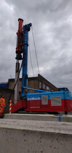
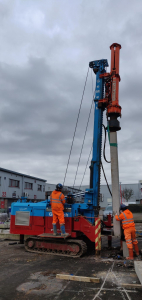
The start of the new year has been frantic at GeMech, with new projects started and large projects continued through January and February, with March looking equally busy and a catalogue of work for April.
January and February has seen us continue CFA piling works for ISG at their prestigious Fairwater Campus development in Cardiff, with load testing completed in January, works are aiming to finish mid-March.
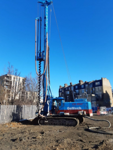
Our largest rig in the fleet, the Comacchio CH450 moved from Cardiff to Stratford to complete CFA piling work for repeat client Watkin Jones on a new student accommodation development.
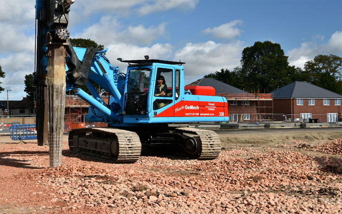
Our driven pile crews have also been busy, utilising our newly adapted precast driven piling rig. GeMech installed 250mm square precast concrete piles to varying depths in Weston-Super-Mare, with further precast driven pile projects on the horizon. Thanks to the versatility of the Vermeer HL2500, the crews have also been busy installing steel cased bottom driven piles for clients LCB Group, ADRA Homes.
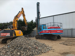
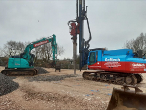
And finally our ground improvement projects have taken off, with our CAT 330 and ABI TM11 being put through their paces installing stone columns in Slough for Francis Construction and Stafford for Spellar Metcalfe. The CAT 330 installing 1,300 stone columns to provide improved ground bearing capacity for two new warehouse units, and the ABI TM11 installing 600 columns. Once completed, these rigs will be moving on to sites in Basingstoke and Bristol, keeping them busy until mid-April.


![]()